

 About Authors:
Lila dhar*1, Surender Jalandra
1 Seth G. L. Bihani S. D. College Of Technical Education,
Institute Of Pharmaceutical Sciences & Drug Research,
Gaganpath, Sri Ganganagar, Rajasthan 335001
*ldbudania@gmail.com
ABSTRACT
Dry heat is sometimes used for sterilization instead of the much more efficient moist heat because some materials are sensitive to moisture. Dry heat is often used to ensure that glass and other laboratory equipment is free of pyrogenic material. The process of sterilization within a chamber or hot air tunnel is a critical process and there is a regulatory requirement for validation of the process in most countries. Validation is defined as the documented procedure of obtaining, recording and interpreting results to ensure that the dry heat sterilization process has been and will be consistently effective. Dry heat sterilizer validation consists of accurately measuring the temperature at critical points within the sterilization chamber throughout the process. Dry heat process generally employs a temperature between 250°C and 400°C for varying time. The sterilizer is required to heat all parts of its load up to the specified temperature for a specified period long enough to achieve the desired sterility.
[adsense:336x280:8701650588]
Reference Id: PHARMATUTOR-ART-1578
INTRODUCTION
Dry heat is one of the most commonly used methods to sterilize and/or depyrogenate pharmaceutical components and products. Dry heat sterilization is often used for heat-stable oils, ointments and powders. Most often, depyrogenation of parenteral containers is performed utilizing a dry heat oven. The depyrogenation process is also utilized on certain heat-stabile components, glass containers, metal equipment, etc. to render the item and final parenteral product free of pyrogens. The equipment utilized to provide the dry heat medium must be validated to ensure that the system is able to provide sterile and/or depyrogenated components, on a reproducible basis. The validation of a dry heat sterilization and depyrogenation process involves approaches and procedures which parallel those utilized for steam sterilization. The efficiency of any heat treatment is determined by the design and source of the heat. Hot air is substantially less efficient in a thermal transfer medium as compared to steam. The validation effort must include heat distribution, heat penetration, bioburden and pyroburden determination, filter integrity, and microbial/endotoxin challenges. [Agalloco James, Carleton Frederick J,]
TYPES OF DRY HEAT STERILIZERS
The types of dry heat sterilizers commonly employed in the pharmaceutical industry are forced-convection batch sterilizers, infrared tunnel sterilizers, forced-convection tunnel sterilizers, continuous flame sterilizers, microwave, and laser/plasma sterilizers.[Sharma P.P,]
General Considerations
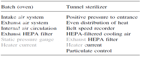
Two types of dry-heat sterilization systems are utilized in the pharmaceutical industry today. They are the conventional hot air oven and the tunnel system. The major difference between the two systems, as far as validation is concerned, is the belt or line speed variable with the tunnel system. The key to validating a dry-heat sterilizer is to prove its repeatability. This means that the unit can consistently perform under a given set of conditions to generate materials that are sterile, pyrogen-free, and particulate-free. Repeatability in dry-heat sterilization obviously involves consistency and reliability in attaining and maintaining a desired temperature. The desired temperature must be reached in all areas of the heating chamber. There will always be an area in the chamber that represents a cold spot; that is, an area that is most difficult to heat up to the desired temperature. This cold spot must be identified so that validation studies involving thermocouple monitoring and microbial challenges can be done at this location. If certain key GMP features of the dry-heat sterilizer are not controlled, with time the cold spot within the sterilizer will change and the key element of validation repeatability cannot be achieved. The GMP features of both the batch oven and tunnel sterilizer that must be controlled before doing any validation studies. Without control of these processes features, validating or even qualifying a dry-heat sterilizer is a total waste of time and money.
As with any sterilization process, the first step in dry-heat sterilizer validation involves qualification of all the equipment and instrumentation used. This step includes examination and documentation of all utilities, ductwork, filters, and control valves or switches for the oven or tunnel unit, and the calibration of the instrumentation used in validating and monitoring the process. The instruments used are as follows:
1. Temperature recorders and thermocouples
2. Constant-temperature baths
3. Amp meters
4. Monometers
5. Dioctylphthalate generators
6. Particle counters
7. Velometers
8. Tachometers
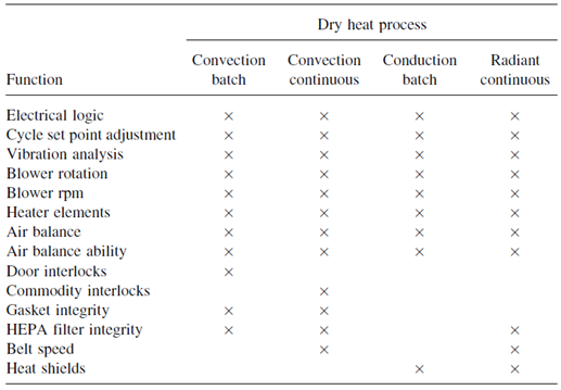
Key Process Features to Control Prior to Validating Dry-Heat Sterilizers
Basic Equipment Performances That Must Be Verified Prior to Calibration-Validation Studies
Validation studies conducted on dry-heat sterilizers can be divided into two basic components. One component envelops all the physical processes, which must be validated, such as temperature control, air particulate levels, and belt speeds. Second component involve the process destroys both microbial and pyrogenic contaminants.
The USP recommends that validation of sterilization cycles for heat stable components include a microbial survival probability of 10K12 of Bacillus subtilis spores. It also recommends that to validate depyrogenation cycles, appropriate items should be charged with a minimum of 1000 EU of purified endotoxin, where the LAL test is used to demonstrate the endotoxin has been inactivated to not more than 1/1000 of the original amount (3-log reduction). The cycles are no longer defined by a minimum time and temperature requirement. Historically, the dry heat sterilization cycles were defined as 1708C for not less than two hours, while depyrogenation cycles were defined at a minimum of 2508C for not less than 30 minutes. A typical cycle might employ temperatures in the range of 1808C to 3008C. The temperatures at the lower end of this range will sterilize, while the higher temperatures in the range are suitable for depyrogenation. The cycle effectiveness will also be dependent on cycle time. The total time for batch cycle completion is often greater than three hours including cooling of the load. [Hugo and Russell’s]
DRY HEAT STERILIZATION
Dry heat is believed to destroy microorganism by causing oxidation.
VALIDATION
Two types of dry-heat sterilization systems are utilized.
The conventional hot air oven
The tunnel system.
BATCH OVEN VALIDATION
1. Air balance determination: Air should be balanced so that positive pressure is exerted to the non sterile side when the door is opened
2. Heat distribution of an empty chamber: Thermocouples should be situated according to a specific predetermined pattern. Repeatability of temperature attainment and identification of the cold spot can be achieved if the temperature range is ±15°C at all monitored locations. Heat-distribution studies can also be conducted as a function of variable airflow rates.
3. Heat-penetration studies:These studies should be designed to determine the location of the slowest heating point within a commodity at various locations of a test load in the sterilizer. Thermocouples are placed in the commodities located in the areas likely to present the greatest resistance to reaching the desired temperature. Normally, three replicate cycles are run at Minimum and maximum temperatures. The cold spot must not move during the replicate studies. Other variations in the cycle affecting heat penetration at the cold spot can be studied, and these might include (a) test load variations, (b) temperature set point variations, and (c) variations in the time of exposure.
4. Mechanical repeatability: During all these studies, mechanical repeatability in terms of air velocity, temperature consistency, and reliability and sensitivity of all the oven and instrumental controls must be verified.
NOW YOU CAN ALSO PUBLISH YOUR ARTICLE ONLINE.
SUBMIT YOUR ARTICLE/PROJECT AT articles@pharmatutor.org
Subscribe to Pharmatutor Alerts by Email
FIND OUT MORE ARTICLES AT OUR DATABASE
TUNNEL STERILIZER VALIDATION
Principles as described above for the physical process validation of batch ovens apply also in the validation of tunnel sterilizers; however, in addition to the variables affecting batch oven validation, tunnel sterilizers have an extra variable-belt speed. This variable can be held constant by maintaining the same belt speed throughout the validation process and not changing it after validation has been completed.
BIOLOGICAL PROCESS VALIDATION OF DRY-HEAT STERILIZATION CYCLES
If a dry-heat process is claimed to produce sterile commodities, micro-organisms known to be most resistant to dry heat must be used to prove the ability of the dry-heat cycle to destroy them at the coolest location in the load. If the dry-heat process is claimed to produce both sterile and pyrogen-free commodities, validation studies must be done using both micro-organisms and microbial endotoxins. The most widely used biological indicators for dry heat have been spores of B. subtilis; however, spores of other bacterial species may be used if they are shown to have greater resistance to dry heat. At 170°C, even the most resistant microbial spore form will have a D value of 6 to 10 min. At temperatures required to depyrogenate, microbial spores will have D values of only a few seconds. The acceptable Z value for microbial dry-heat resistance is 20°C.
A suggested step-by-step sequence in the microbial validation of a dryheat process for sterilizing and depyrogenating large-volume glass containers by a convection batch oven is presented.
This process include following steps:
Select the type of biological indicator to be used in monitoring process lethality. Calibrate the biological indicator in its carrier medium.
Place spore carrier in approximately 12 glass bottles located at the previously determined coolest area of the oven.
Run a complete cycle using the desired loading pattern for future dry heat overkill cycles.
After the cycle, aseptically transfer the spore strip to vessels of culture media and also use appropriate positive and negative controls.
Determine the number of survivors by plate-counting or fraction negative methods.
Use following Eqn to determine the number of spore log reduction (SLRs):

ENDOTOXIN CHALLENGE IN THE VALIDATION OF DRY-HEAT STERILIZERS
The most controversial aspect of endotoxin challenge testing is how much endotoxin challenge to use.
The step-by-step procedure for the endotoxin validation of a dry-heat process may be as follows:
1. Inoculate commodity samples with a known amount of endotoxin (e.g., 10–100 ng Escherichia coli lipopolysaccharide, obtainable from several commercial sources). The endotoxin should be contained in a volume of water equal to the residual water volume following the washing procedure used prior to sterilization.
2. Thermocouples should be placed in commodities adjacent to those containing endotoxin for temperature monitoring and correlation with LAL test results.
3. Endotoxin destruction should be ascertained at the coolest location of the load. Load configurations should be identical to those used in the microbial validation studies.
4. Several endotoxin challenge samples should be done per cycle, and the studies must be adequately replicated (3–5 repeats).
5. Following the dry-heat cycle, aseptically transfer the units containing endotoxin to an aseptic area for extraction procedures, sampling, and conducting the limulus amebocyte lysate (LAL) test.
6. F values required for endotoxin destruction at various temperatures and/or cycle time–temperature variations can be determined using a Z value of 54°C and the following equation:
Fendo. = Δt Σ 10(T−170)/54
When the validation studies described in this section have been completed, all data are analyzed and a decision is made concerning their acceptability. If acceptable, the entire validation procedure and all appropriate supporting data are documented in a bound manual. If the studies are unacceptable because of unsubstantiated claims of the process or a lack of reproducibility, further testing must be performed or process variables changed followed by additional validation studies.
The final document will be reviewed and approved by various plant disciplines (engineering, microbiology, production, etc.) before the dry-heat sterilizer is considered fully validated and released for use. [Nash Robert A, Wachter Alfred H,]
|
YOUR COMPANY VALIDATION STANDARD OPERATING PROCEDURE |
SOP No. Val. 700.20 Effective date: mm/dd/yyyy
Approved by:
TITLE: Hot Air Sterilization Tunnel Certification and Validation Guideline
AUTHOR: _________________________________________
Name/Title/Department
_________________________________________
Signature/Date
CHECKED BY: _________________________________________
Name/Title/Department
_________________________________________
Signature/Date
APPROVED BY:________________________________________
Name/Title/Department
_________________________________________
Signature/Date
REVISIONS:
|
No. |
Section |
Pages |
Initials/Date |
|
|
|
|
|
|
|
|
|
|
|
|
|
|
|
SOP No. Val. 700.20 Effective date: mm/dd/yyyy
Approved by:
SUBJECT: Hot Air Sterilization Tunnel Certification and Validation Guideline
Purpose
To provide a written procedure to be used as a guideline for the certification and validation of a dry heat sterilizer
Responsibility
It is the responsibility of production manager, validation manager and concerned departmental managers to follow the procedure. The quality assurance manager is responsible for SOP compliance.
Introduction
Laminar flow sterilization tunnels are widely used in high-speed aseptic manufacturing. Typically, laminar flow tunnels contain three sections: 1. preheating, 2. heating, and 3. cooling.
Sterilization occurs at temperatures higher than 300°C in the heating section. After sterilization, cooling is necessary before container filling. It is therefore very important to keep conditions sterile in the cooling section (up to the filling station) by keeping the cooling section at a slight positive pressure towards the tunnel room (2 to 3 Pa). A higher overpressure would result in cooling the heating section with cooling air, decreasing the sterilization efficiency of the heating section.
The certification activities include a series of process documentation and qualification studies that start with the initial installation of a sterilization system and continue as process engineering changes or new or revised product introductions are required. Qualification activities comprise installation, operational, change, and performance phases.
Procedure
1. Installation Qualification (IQ)
The initial IQ hot air sterilizer tunnel certification shall consist of the development of the following information package:
Hot air sterilizer tunnel dimensions
Product carrier description
Utility support system description
Sterilizer equipment description
Equipment control system description
2. Process Description
Description of the sterilization medium employed
Description of the cycle steps and process functions initiated during the sterilization process
Type of process control employed, i.e., time and temperature or product container control
System operating procedures and system flow diagrams.
SOP No. Val. 700.20 Effective date: mm/dd/yyyy
Approved by:
3. Product Safety
To confirm that product safety considerations have been addressed, review of tunnel construction and operation materials for product contact potential or suitability shall be documented. Tunnel construction materials, which contact the sterilization medium, shall be identified. This would include:
Product carriers
All exposed potential medium contact surfaces including heating and cooling sections
Heat generating, cooling, and conveying system
Equipment lubricants with potential product contact implications must be verified as not jeopardizing product integrity. Lubricants should be identified.
4. CRITICAL PROCESS INSTRUMENTATION LIST
Temperature control and monitoring systems
Pressure control and monitoring systems
Carrier drive monitoring systems
Critical system alarms
The following equipment installation qualification checks shall be performed:
4.1 DOP TESTS OF HEPA FILTERS
Test objective
To demonstrate that HEPA filters are properly installed by verifying the absence of bypass leakage and other defects such as tears and pinhole leaks
Test method
This test is performed only by certified or previously trained personnel who introduce DOP aerosol upstream of the filter through a test port and search for leaks downstream with an aerosol photometer. Filter testing is performed after operational air velocities have been verified and adjusted where necessary.
NOW YOU CAN ALSO PUBLISH YOUR ARTICLE ONLINE.
SUBMIT YOUR ARTICLE/PROJECT AT articles@pharmatutor.org
Subscribe to Pharmatutor Alerts by Email
FIND OUT MORE ARTICLES AT OUR DATABASE
Align the aerosol photometer as follows:
1. Position the smoke generator so the DOP aerosol will be introduced into the air stream ahead of the HEPA filters.
2. Open the appropriate number of nozzles until a DOP challenge concentration of 100 mg/l of air is reached. This challenge concentration is measured upstream of the HEPA filter, and is evidenced by a reading of between 4 and 5 on the logarithmic scale of the aerosol photometer.
3. Scan each filter by holding the photometer probe approximately 1 in. from the filter face and passing the probe in slightly overlapping strokes at a traverse rate of not more than 10 ft/min, so that the entire face is sampled.
4. Make separate passes with the photometer probe around the entire periphery of the filter, along the bond between the filter medium and the frame, and along all other joints in the installation through which leakage might bypass the filter medium.
Acceptance criteria
Entrance section filters and cooling section filters
Local DOP penetration ð 0.01% of the upstream concentration
Heating section filters
SOP No. Val. 700.20 Effective date: mm/dd/yyyy
Approved by:
Local DOP penetration ð 0.1% of the upstream concentration provided that local results of hot tunnel particle counting air cleanliness classification are within specifications (particle counts at any location of the heating section ð 100 particles Š 0.5 m/ft3 and zero particle Š 5 m/ft3)
Equipment
DOP polydisperse aerosol is generated by blowing air through liquid dioctylphthalate (DOP) at room temperature. The approximate light scattering mean droplet size distribution of the aerosol is 99% + less than 3.0 m and 95% + less than 1.5 m.
The DOP aerosol generator is compressed-air operated, equipped with Laskin–type nozzles. The aerosol photometer is a light-scattering type with a threshold sensitivity of at least 10–3 mg/l, capable of measuring concentrations in the range of 80 to 120 mg/l, and with air sample flow rate of 1 ft3 + 10% per min. This instrument is to be calibrated per manufacturer recommendation.
4.2 Air velocity and homogeneity at the exit of HEPA filters
Test objective
To demonstrate that air speed is homogeneous in each section of the tunnel (entrance, heating, cooling). The air speed values and homogeneity are important for uniform heating (sterilization) and uniform cooling of glass containers.
Test method
Draw a grid on the floor of tunnel.
Measure and record the velocity at the center of each grid at the specified heights.
Allow no objects near the anemometer, except for built-in equipment.
Measurements should be taken for a minimum of 15 sec.
Record the pressure readings (in in.) from the manometer connected to the module’s plenum.
Equipment
Hot-wire anemometer and stand
Acceptance criteria
From left to right, speed variation should not be more than 30% around the mean. From each filter the speed uniformity must be greater than ± 20% relative to the mean, per filter not more than one location out of this limit.
4.3 Air velocity and uniformity on the tunnel conveyor
Test objective
To demonstrate that air flow is continuous from top to bottom along the whole surface of the conveyor (air flow from bottom to top would contaminate glassware with particles from the conveyor and machinery)
Test method
Draw a grid on the floor of tunnel.
Measure and record the velocity at the center of each grid at the specified heights.
Approved by
Allow no objects near the anemometer, except for built-in equipment.
Measurements should be taken for a minimum of 15 sec
Record the pressure readings (in in.) from the manometer connected to the module’s plenum.
Equipment
Hot-wire anemometer and stand
Acceptance criteria
There should be no measured speed at any point from the bottom to the top (anemometer). No opposite flow should be visualized with the Drager tube and pump. It is preferable that left to right speed variation be lower than 30% around the mean. The number of points out of this limit is to be minimized.
4.4 Hot tunnel particle countings
Test objective
To demonstrate that the air handling system of the tunnel (hardware and software) is able to produce at the level of the top of the container a class 100 air on all the surface of the conveyor.
Test method
These tests are performed after the HEPA filter leak tests and air velocity tests are completed.
To obtain baseline data with the room in static conditions, perform the following tests with operational personnel absent and the equipment at rest:
1.Using the particle analyzer, count particles greater than or equal to 0.5 m in diameter at heights of 40 in. in the center of each grid.
2.If the particle count in the 0.5 m range is less than 50 per ft3 of air, four additional counts at this location are taken to place these particle counts within a 50% confidence interval.
After completion of these tests, if the absolute air filtration modules are operating within accepted limits, repeat steps 1 and 2 with operational personnel present and the fill equipment running. If at any time there is a deviation from accepted parameters, the various components of the systems in operation are reviewed, repaired, or adjusted until the desired conditions are achieved.
Equipment
Laser particulate counter
Acceptance criteria
All locations with particle counts:
ð 100 particle Š 0.5 m/ft3
zero particle Š 5 ?? m/ft3
SOP No. Val. 700.20 Effective date: mm/dd/yyyy
Approved by:
4.5 Empty tunnel heat distribution
Test objective
The objective of the empty distribution runs will be to evaluate:
Heating characteristics of the sterilizer, product carrier system, and the sterilization medium employed
Ability of the sterilizer to hold the required sterilization parameters
Ability of the sterilization cycle control mechanisms to operate as intended
Test method
A review of all sterilization specifications assigned to the sterilizer under consideration shall be made, with the specifications cycle requiring the maximum peak dwell temperature and heating rate to be selected for the empty sterilizer heat distribution runs. During the empty sterilizer heat distribution runs, sterilizer parameters and equipment component status shall be visually monitored to confirm applicable control operations.
Technical criteria
Fixed thermocouples shall be located at key sterilizer positions, as justified by the sterilizer operation and control characteristics (i.e., at exhaust or vent line, in recirculation heating medium line, next to controller sensor, as applicable).
Distribution thermocouples for sterilizer shall be located throughout the chamber per plan and traceable location diagram. Sufficient functional thermocouples shall be used during distribution runs conducted in sterilizer to assure adequate distribution determination.
Traveling temperature sensors for continuous sterilizer shall be located throughout the conveyor system per plan and traceable placement diagram. The temperature sensors shallbe placed in various locations within each distribution run.
Heat distribution data shall include evaluation of the coldest and hottest sterilizer zones, the mean distribution temperature observed, the range of distribution temperatures observed, and the heat-up and cool-down times obtained.
Acceptance criteria
The distribution runs must meet the time and temperature requirements of the corresponding specifications or operating procedures.
All function initiations required during the operating modes must have occurred as specified.
SOP No. Val. 700.20 Effective date: mm/dd/yyyy
Approved by:
4.6 System alarm and safeguard checks
Test objective
To confirm that all alarm feature input and output loops function as intended
Test method
All alarm features available on the sterilizer system under consideration, both program controlled or separately wired, shall be challenged to confirm appropriate functionality.
Technical criteria
Where possible, each alarm and safeguard feature should be challenged by simulation of actual alarm conditions within the sterilizer equipment system. Where simulation of physical alarm conditions would be impractical, alarm circuitry may be challenged by use of electrical input signals.
The following alarm and safeguard systems should be checked, as applicable:
Power or electrical system interruption alarms
Chamber door-open alarms
Cycle sequence alarms
Timer system alarms
High or low temperature alarms
Chain speed and R.P.M. alarms
Fan-on alarms
Computer or controller data entry safeguard system alarms
Acceptance criteria
All alarm and safeguard features shall respond to their corresponding system condition signal as specified.
Support documentation
The following documents shall be included in the IQ certification package:
Sterilizer engineering drawings
Sterilizer operation procedure
Sterilizer sanitization procedure
Sterilizer maintenance procedures
Sterilizer specification utilization list
Distribution thermocouple location diagrams
Temperature sensing unit location diagram (continuous sterilizers)
Sterilizer process log sheets
Empty chamber heat distribution test data summaries
Copy of appropriate specifications used
Test data summary sheets for each function evaluation
Test and equipment pre- and postcalibration status listings
SOP No. Val. 700.20 Effective date: mm/dd/yyyy
Approved by:
5. Operational Qualification (OQ)
5.1 Background
The intent of sterilizer OQ studies will be to:
Confirm that sterilizers are capable of processing at established time and temperature ranges that assure conformance with respective specification requirements
Confirm that established sterilization cycles deliver a uniform and reproducible heat input to products assigned to each cycle
The sterilization test functions required to qualify or validate the sterilizer will include process heat distribution, process heat penetration, and process microbial and depyrogenation validation, as applicable.
The OQ phase of sterilizer validation shall consist of the development of an information package fulfilling the documentation requirements of the generic equipment operational qualification. The following sterilizer- specific documentation shall be incorporated in the operation qualification:
Brief sterilizer equipment or process description shall be included for initial certification.
The products utilized for testing subsection shall include a listing of the items used for OQ test function runs and items utilized for sterilizer bulking during test function runs.
The sterilizer utilization list subsection shall include a listing of the sterilization cycles being validated and the corresponding product list numbers assigned to each specification.
The sterilizer utilization list and the following OQ test requirements summary will be utilized to determine the products assigned to the sterilizer that shall be subjected to the type and number of test function runs required to establish overall sterilizer qualification or validation. The test function subsections shall include test objectives, test methods and acceptance criteria, as follows.
NOW YOU CAN ALSO PUBLISH YOUR ARTICLE ONLINE.
SUBMIT YOUR ARTICLE/PROJECT AT articles@pharmatutor.org
Subscribe to Pharmatutor Alerts by Email
FIND OUT MORE ARTICLES AT OUR DATABASE
5.2 Heat distribution
Test objective
To evaluate the heating characteristics of the tunnel, carrier system, and sterilization medium employed under loaded conditions
Test method
Distribution thermocouples shall be located in each run as described in IQ empty tunnel heat distribution runs.
All distribution runs shall be performed, monitored, and documented in accordance with the respective sterilizer operating procedure.
SOP No. Val. 700.20 Effective date: mm/dd/yyyy
Approved by:
Acceptance criteria
All distribution runs must meet the parameter requirements of the corresponding specification and established production sterilization cycle.
5.3 Heat penetration
Test objective
To evaluate the heating characteristics of items within the tunnel when subjected to the sterilization medium
To evaluate the relative heating characteristics of items and reference thermocouples where applicable
To establish production work order sterilization parameters
Test method
Heat penetration runs may be conducted in conjunction with required heat distribution runs.
Thermocouple or temperature sensor probes shall be placed within the penetration test containers in accordance with established written container preparation procedures. Test containers may be trays, pans, commodities, etc., depending upon the testing required.
Thermocouple and temperature sensor probe placement within the containers shall be documented.
Where applicable, thermocouple placement shall be in the container cold zone, as determined from generated container mapping studies.
Each heat penetration run shall include thermocouple temperature sensor probe containers distributed throughout the tunnel, per planned and traceable location diagram.
The number of heat penetration test containers per run shall agree with that required for heat distribution thermocouples.
If previous empty tunnel heat distribution test runs have identified hot or cold zones, at least one of the penetration test containers must be placed in each of these zones per run.
The heat penetration sample containers shall be loaded into the tunnel carrier in an orientation consistent with planned production run loading and the corresponding container heat mapping study loading method.
Acceptance criteria
All heat penetration data collected during each run must meet the requirements for the corresponding specification.
The production operating ranges and windows established from the heat penetration runs must assure all products in the test runs will meet the calculated requirements for the corresponding specification. If a satisfactory operating range is not established using minimum and maximum loading parameters, intermediate loading conditions must be tested.
Where tunnel peak dwell temperature and time are to be used for routine production cycle control, or as back-up control, correlation of sterilizer peak dwell time and temperature with the hottest and coldest profile container must be shown for each run, where applicable.
SOP No. Val. 700.20 Effective date: mm/dd/yyyy
Approved by:
5.4 Componentry microbial or pyrogen challenges
Test objective
To confirm the biological relationship between parametrically determined process lethalities, by demonstrating the ability of the sterilizer to effectively reduce the challenge material to an acceptable level
Test method
1. Componentry microbial challenges
The number of challenge containers, preparation methods, spore crop type, and inoculation levels described in the appropriate documentation shall be followed in the production of test items for each run.
Heat penetration test containers of corresponding container size and type and fill volume shall be placed adjacent to the challenge test items in each run.
At least one set of microbial challenge or penetration test containers shall be placed in the sterilizer cold zone per run (where applicable).
Test container placement shall be defined per planned and traceable location diagrams.
Maximum sterilizer loading configurations shall be used when conducting challenge test runs.
The corresponding production cycle time and temperature control parameters that deliver subminimal specification conditions shall be utilized when conducting the challenge runs.
If absolute minimum time and minimal temperature parameters are not used during the componentry challenge runs, manufacturing order parameter limits must reflect the parameters used during these runs.
2. Componentry pyrogen challenges
The number of challenge containers, preparation methods, endotoxin identification, and inoculation levels described in the appropriate documentation shall be followed in the production of test items for each run.
Heat penetration test containers of corresponding container size and type and fill volume shall be placed adjacent to the challenge test items in each run.
At least one set of pyrogen challenge or penetration test containers shall be placed in the sterilizer cold zone per run where applicable.
Test container placement shall be defined per planned and traceable location diagrams.
Maximum sterilizer loading configuration shall be used when conducting challenge test runs in allother sterilizers.
The corresponding production cycle time and temperature control parameters that deliver sub minimal specification conditions shall be utilized when conducting the challenge runs.
Acceptance criteria
A minimum microbial challenge spore log reduction of equal to or greater than six must beshown for each run.
A minimum pyrogen challenge must be equal to or greater than three log reductions for each run.
At least 15% ofthe required functional container time and temperature values must show subminimal process conditions, per run.
Coldzone temperature correction must be used where applicable.
5.5 Support documentation
The following documents shall be included in each operational qualification certification package, as applicable:
Sterilizer operating procedure
Current sterilizer utilization list
Copies of the specifications used during the OQ function test runs
Copies of all penetration distribution and challenge thermocouple placement diagrams
SOP No. Val. 700.20 Effective date: mm/dd/yyyy
Approved by:
Description of the bulking items used, whereapplicable
Copies of allmicrobial challenge protocols, which should include identification ofthe types, crop numbers, and D values for the biological indicators used
Copies of all pyrogen challenge protocols, which should include materials used, lot number, sensitivity, and inoculation levels
Key test and equipment instrumentation pre- and post calibration status supporting each function
Test data summaries
The temperature data collected during each operational qualification run shall be summarized so that the following information, as applicable, can be readily determined for each run:
Sterilizer heat-up time
Duration of sterilizer peak dwell
Minimum and maximum sterilizer temperatures during peak dwell
Sterilizer cool-down time
Commodity or component heat-up time
Peak dwell residence time or carrier speed
Minimum and maximum item temperature during peak dwell
Process Engineering Change Qualification
Modifications to sterilizer equipment systems shall be accompanied by initiation and completion of a formal engineering change request and authorization documentation package. Plant engineering, manufacturing and quality assurance shall be responsible for determining whether a change impacts the certified functions of the sterilizer.
Frequency
Initial validation: three times
Revalidation: twice per year
Reasons for Revision
Effective date: mm/dd/yy
First time issued for your company, affiliates, and contract manufacturers.
[Althea Mcleary;]
REFERENCE
1. Agalloco James, Carleton Frederick J, “Validation Of Pharmaceutical Process” 3rd Edition, Published By Informa healthcare, New York, Page No.223-225
2. Sharma P.P. “Practice GMPs A Guide For cGMP Compliance” 5th Edition 2006 Published By Vandana Publication Pvt. Ltd. Delhi. Page No.286-288
3. Hugo And Russell’s Pharmaceutical microbiology” 7th Edition, Published By Blackwell Sciences, Page No.355-356, 366-370
4. Nash Robert A, Wachter Alfred H, Pharmaceutical Process Validation” Volume 129, 3rd Edition Published By Marcel Dekker, New York, Page No. 102-110
5. Sharma P.P, Validation In Pharmaceutical Industry, 1st Edition 2007, Published By Vandna Publication Pvt. Ltd, Delhi Page No. 303-309.
NOW YOU CAN ALSO PUBLISH YOUR ARTICLE ONLINE.
SUBMIT YOUR ARTICLE/PROJECT AT articles@pharmatutor.org
Subscribe to Pharmatutor Alerts by Email
FIND OUT MORE ARTICLES AT OUR DATABASE