

ABOUT AUTHORS:
Arshad Hala
Seth G. L. Bihani S. D. College of Technical Education,
Institute of Pharmaceutical Sciences & Drug Research,
Gaganpath, Sri Ganganagar, Rajasthan -335001, India
ABSTRACT:
HPTLC is one type of planar chromatography and most advanced form of instrumental TLC. Now a day, HPTLC is more useful than TLC and HPLC. Because HPTLC is independent of sample application, chromatogram development, detection, etc. it is not only instrumental TLC but entire concept that include widely standardize methodology based on validated method. It is instrument controlled by software. In this review article, we discussed about which type of instrument used in HPTLC, complete HPTLC methodology, How HPTLC better than TLC.
[adsense:336x280:8701650588]
REFERENCE ID: PHARMATUTOR-ART-1260
INTRODUCTION:
Planar Chromatography as opposed to column chromatography (e.g. GC, HPLC) utilizes a flat (planar) stationary phase for separation. In Thin-Layer Chromatography (TLC) this stationary phase is supported by a glass plate or a foil (plastic or aluminum). Again unlike column separations, the TLC plate constitutes an open system, which passes through the individual steps of the TLC analysis in an off-line mode.
The relative independence of sample application, chromatogram development, detection, etc. in time and location makes possible the parallel analysis of many samples on the same plate. The most advanced form of instrumental TLC is commonly called high performance thin-layer chromatography (HPTLC), but the term does not simply imply instrumental TLC on special high performance layers. HPTLC is an entire concept that includes a widely standardized methodology based on scientific facts as well as the use of validated methods for qualitative and quantitative analysis. Sophisticated instruments, controlled by an integrated software platform ensure to the highest possible degree the usefulness, reliability, and reproducibility of generated data. HPTLC is therefore the term for a method that meets all quality requirements of today’s analytical labs even in a fully regulated environment.
Initial costs for an HPTLC system as well as maintenance, and cost per sample still remain comparatively low and all advantages derived from the planar separation principle are certainly maintained. the possibility of visual evaluation of separated samples on the plate is one of the most valuable aspects of TLC. It reaches a completely new dimension in HPTLC through the use of modern techniques for generating and evaluating digital images.1
FEATURES OF HPTLC:
The advantages of this off-line arrangement as compared with an on-line process, such as column high-performance liquid chromatography (HPLC), have been outlined and include the following:
• Technically, it is simple to learn and operate.
• Several analysts work simultaneously on the system.
• Lower analysis time and less cost per analysis.
• Low maintenance cost.
• Visual detection possible – as it is an open system.
• Availability of a great range of stationary phases with unique selectivity for mixture components. Chromatographic layer (sorbent) requires no regeneration as TLC/HPTLC plates are disposable.
• Ability to choose solvents for the mobile phase is not restricted by low UV transparency or the need for ultra-high purity. Corrosive and UV-absorbing mobile phases can be employed.
• No prior treatment for solvents like filtration and degassing.
• There is no possibility of interference from previous analysis as fresh stationary and mobile phases are used for each analysis. No carry over, hence no contamination.
• Repetition of densitometric evaluation of the same sample can be achieved under different conditions without repeating the chromatography to optimize quantification, since all sample fractions are stored on the TLC/HPTLC plate.
• Samples rarely require cleanup.
• High sample throughput since several samples can be chromatographed simultaneously.
• Lower expenditure of solvent purchase and disposal since the required amount of mobile phase per sample is small. In addition, it minimizes exposure risks of toxic organic effluents and reduces possibilities of environment pollution.
• Accuracy and precision of quantification is high because samples and standards are chromatographed and measured under the identical experimental conditions on a single TLC/HPTLC plate.
• Sensitivity limits of analysis are typically at nanogram (ng) to pictogram (pg) levels.
• Use of different universal and selective detection methods.3
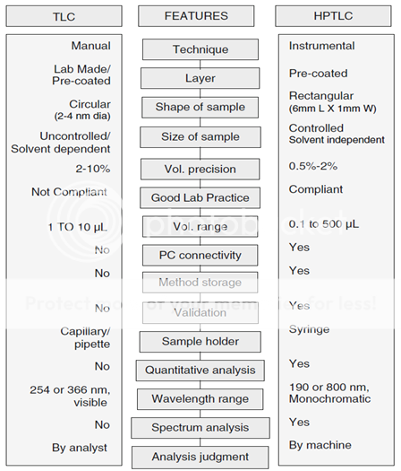
HPTLC is a modern adaptation of TLC with better and advanced separation efficiency and detection limits. The table below compares HPTLC and TLC (Table 1).
Table.1: Comparison of TLC and HPTLC.3
HPTLC METHODOLOGY:
Set the analytical objective first that may be quantification or qualitative identification or separation of two components/multicomponent mixtures or optimization of analysis time before starting HPTLC. Method for analyzing drugs in multicomponent dosage forms by HPTLC demands primary knowledge about the nature of the sample, namely, structure, polarity, volatility, stability, and the solubility parameter. Method development involves considerable trial and error procedures. The most difficult problem usually is where to start, with what kind of mobile phase.
Selection of stationary phase is quite easy, that is, to start with silica gel which is reasonable and nearly suits all kind of drugs. Mobile phase optimization is carried out by using three level techniques. First level involves use of neat solvents and then by finding some such solvents which can have average separation power for the desired drugs. Second level involves decreasing or increasing solvent strength using hexane or water for respective purposes. Third level involves trying of mixtures instead of neat solvents from the selected solvents of first and second level which can further be optimized by the use of modifier like acids or bases.
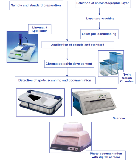
Analytes are detected using fluorescence mode or absorbance mode. But, if the analytes are not detected perfectly than it needs change of stationary phase or mobile phase or need the help of pre or post chromatographic derivatization. Optimization can be started only after a reasonable chromatogram which can be done by slight change in mobile-phase composition. This leads to a reasonable chromatogram which has all the desired peaks in symmetry and well separated. Procedure for HPTLC method development is outlined as follow (Figure 1).3
SCHEMATIC PROCEDURE FOR HPTLC METHOD DEVELOPMENT
STATIONARY PHASE:
HPTLC can be regarded as the most advanced form of modern TLC. It uses HPTLC plates featuring small particles with a narrow size distribution. As a result, homogenous layers with a smooth surface can be obtained. HPTLC uses smaller plates (10 × 10 or 10 × 20 cm) with significantly decreased development distance (typically 6 cm) and analysis time (7–20 min). HPTLC plates provide improved resolution, higher detection sensitivity, and improved in situ quantification and are used for industrial pharmaceutical densitometric quantitative analysis.
Normal phase adsorption TLC on silica gel with a less polar mobile phase, such as chloroform– methanol, has been used for more than 90% of reported analysis of pharmaceuticals and drugs. Lipophilic C-18, C-8, C-2; phenyl chemically-modified silica gel phases; and hydrocarbon- impregnated silica gel plates developed with a more polar aqueous mobile phase, such as methanol–water or dioxane–water, are used for reversed-phase TLC.
Other precoated layers that are used include aluminum oxide, magnesium silicate, magnesium oxide, polyamide, cellulose, kieselguhr, ion exchangers, and polar modified silica gel layers that contain bonded amino, cyano, diol, and thiol groups.
Optical isomer separations that are carried out on a chiral layer produced from C-18 modified silica gel impregnated with a Cu (II) salt and an optically active enantiomerically pure hydroxyproline derivative, on a silica layer impregnated with a chiral selector such as brucine, on molecularly imprinted polymers of a-agonists, or on cellulose with mobile phases having added chiral selectors such as cyclodextrins have been reported mostly for amino acids and their derivatives.
Mixtures of sorbents have been used to prepare layers with special selectivity properties. HPTLC plates need to be stored under appropriate conditions. Before use, plates should be inspected under white and UV light to detect damage and impurities in the adsorbent. It is advisable to prewash the plates to improve the reproducibility and robustness of the results.3
MOBILE PHASE:
The selection of mobile phase is based on adsorbent material used as stationary phase and physical and chemical properties of analyte.
General mobile-phase systems that are used based on their diverse selectivity properties are diethyl ether, methylene chloride, and chloroform combined individually or together with hexane as the strength-adjusting solvent for normal-phase TLC and methanol, acetonitrile, and tetrahydrofuran mixed with water for strength adjustment in reversed-phase TLC.
Separations by ion pairing on C-18 layers are done with a mobile phase such as methanol–0.1 M acetate buffer (pH 3.5) containing 25 mM sodium pentanesulfonate (15.5:4.5).
Accurate volumetric measurements of the components of the mobile phase must be performed separately and precisely in adequate volumetric glassware and shaken to ensure proper mixing of the content.
Volumes smaller than 1 ml are measured with a suitable micropipette. Volumes up to 20 ml are measured with a graduated volumetric pipette of suitable size. Volumes larger than 20 ml are measured with a graduated cylinder of appropriate size. To minimize volume errors, developing solvents are prepared in a volume that is sufficient for one working day. 3
NOW YOU CAN ALSO PUBLISH YOUR ARTICLE ONLINE.
SUBMIT YOUR ARTICLE/PROJECT AT articles@pharmatutor.org
Subscribe to Pharmatutor Job Alerts by Email
FIND OUT MORE ARTICLES AT OUR DATABASE
LAYER PREWASHING:
Plates are generally handled only at the upper edge to avoid contamination. Usually plates are used without pretreatment unless chromatography produces impurity fronts due to contamination of the plate. For reproducibility studies and quantitative analysis, layers are often prewashed using 20 ml methanol (generally, methanol is used as a prewashing solvent; however, a mixture of methanol and ethyl acetate or even mobile phase of the method may also be used) per trough in a 20 × 10 cm twin-trough chamber (TTC). Up to two 20 × 10 cm or four 10 × 10 cm plates can be developed back-to-back in each trough of the TTC.
Remove the plate and dry it for 20 min in a clean drying oven at 120?C. Equilibrate plate with laboratory atmosphere (temperature, relative humidity) in a suitable container providing protection from dust and fumes. 3
PREPARATION OF PLATE:
Precoated layers: TLC plates can be made in any lab with suitable apparatus. However such layers do not adhere well to the glass support. Precoated plates that use small quantities of very high molecular weight polymer as binder overcomes most limitations of a home-made layer. Precoated layers are reasonably abrasion resistant, very uniform in layer thickness, reproducible, preactivated, and ready to use. They are available with glass or aluminum or polyester support. Aluminum foil plates are less expensive to buy, cheaper, can be cut, and therefore easy to carry around or transport or mail. Glass plates are the best for highest quality of results. Most often, layers containing a fluorescent indicator F 254 are used. This enables the visualization of samples in a UV cabinet very simply, instantly, and in a nondestructive manner.Commonly used size of plates in TLC is 20×20 cm and in HPTLC 20 × 10 cm or 10 × 10 cm is widespread.
Plate Size
20 ×10 cm or 10 ×10 cm.
Plate support – glass or aluminum with florescent indicator. (M.M. Shrivastava, 2010-2011)
SAMPLE PREPARATION AND APPLICATION:
Sample application
In Thin-Layer Chromatography manual sample application with capillaries is usually performed for simple analyses. Sample volumes of 0.5 to 5 μL can be applied as spots onto conventional layers without intermediate drying. HPTLC layers take up to 1 μL per spot. More demanding qualitative, quantitative, and preparative analyses or separations are made possible only by instruments for bandwise application of samples using the spray-on technique. Particularly HPTLC takes full advantage of the gain in separation power and reproducibility available by precise positioning and volume dosage.1
Sample application in the form of bands or rectangles
Spraying-on samples as narrow bands allows the application of significantly larger volumes. Any zone broadening that would typically be caused by chromatography during application by contact spotting can be excluded. In special cases, such as trace analysis, very large sample volumes or samples with a high matrix content can be sprayed-on in the form of rectangles which, prior to chromatography, are focused into narrow bands with one short development step with a solvent of high elution strength.1
ATS 4 OR LINOMAT 5?
The Linomat 5 as a stand-alone device is the ideal instrument for sample application for instrumental and preparative Thin-Layer Chromatography. The software controlled version allows stepping up to HPTLC. Being a semi-automatic device, the Linomat 5 represents a less expensive Alternative to the Automatic TLC Sampler (ATS 4) without compromising on the available quality of applied zones. The ATS 4 is commonly used if many samples have to be analyzed and if there is more demand for flexibility of the application. Whether it is switching from spot to bandwise or to rectangular application patterns, or whether changing complex application sequences from plate to plate, the ATS 4 is up to the task. That makes the ATS 4 not only the most powerful application device for the routine HPTLC facility but also for the demanding and flexible research laboratory. In connection with the ATS 4‘s Free Mode software even non-TLC tasks can be performed such as applications onto nitrocellulose membranes for the production of diagnostic kits.1
LINOMAT 5
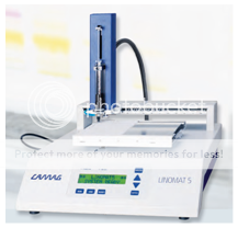
Figure.3: Linomat.51
The Linomat 5 offers semi-automatic sample application for qualitative and quantitative analyses as well as for preparative separations. The instrument is suitable for routine use for medium sample throughput. In contrast to the Automatic TLC Sampler (ATS 4), changing the sample for the Linomat requires presence of an operator.
Spray-on technique:
With the LINOMAT samples are sprayed onto the chromatographic layerin the form of narrow bands. This technique allows larger volumes to beapplied than by contact transfer (spotting). during the spraying the solventof the sample evaporates almost entirely concentrating the sample intoa narrow band of selectable length. Starting zones sprayed on as narrowbands ensure the highest resolution attainable with any given thin-layerchromatographic system. For qualitative and quantitative HPTLC as wellas for demanding preparative separation spray-on application as bandsis a necessity.
Key features:
• Operation in standalone mode or under WINCATS.
• sample application as narrow bands using the spray-on technique.
• Application of solutions onto any planar medium.
• Semi-automatic operation, only changing of sample (cleaning, filling and replacing the syringe) is performed manually.1
AUTOMATIC TLC SAMPLER 4 (ATS 4)
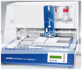
Figure.4: Automatic TLC sampler.41
Automatic sample application is a key factor for productivity of the HPTLC laboratory. The requirements for an instrument serving this purpose, i.e. precision, robustness during routine use and convenient handling are fully met by the Automatic TLC Sampler 4. The ATS 4 offers fully automatic sample application for qualitative and quantitative analyses as well as for preparative separations. it is suited for routine use and high sample throughput in mass analysis. Samples are either applied as spots through contact transfer (0.1–5 μl)or as bands or rectangles (0.5 to > 50 μl) using the spray-on technique.Starting zones sprayed on as narrow bands offer the best separation attainablewith a given chromatographic system. Application in the form of rectanglesallows precise application of large volumes without damaging thelayer. Prior to chromatography, these rectangles are focused into narrowbands with a solvent of high elution strength.The ATS 4 allows «over spotting», i.e. a sequential application from differentvials onto the same position. This technique can be used e.g. in prechromatographicderivatization, spiking, etc.
Key features:
• Fully automatic sample application, suitable for routine.
• Application of spots, bands, or rectangles.
• Data input and monitoring through WINCATS.
• Application of solutions onto any planar medium.
• Application of sample volumes between 0.1 and 5 μl by contact transfer.
• spray-on application of sample volumes between 0.5 and > 50 μl.1
DEVELOPMENT OF CHROMATOGRAM:
Thin-layer chromatography differs from all other chromatographic techniques in the fact that in addition to stationary and mobile phases, a gas phase is present. This gas phase can significantly influence the result of the separation.
Processes in the Developing Chamber
The «classical» way of developing a chromatogram is to place the plate ina chamber, which contains a sufficient amount of developing solvent.
The lower end of the plate should be immersed several millimeters. Drivenby capillary action the developing solvent moves up the layer until the desiredrunning distance is reached and chromatography is stopped. The followingconsiderations primarily concern silica gel as stationary phase anddevelopments, which can be described as adsorption chromatography.
Provided the chamber is closed, four partially competing processes occur:
1. Between the components of the developing solvent and their vapor, anequilibrium will be established eventually (1). This equilibrium is calledchamber saturation. Depending on the vapor pressure of the individualcomponents the composition of the gas phase can differ significantlyfrom that of the developing solvent.
2 While still dry, the stationary phase adsorbs molecules from the gas phase.This process, adsorptive saturation, is also approaching an equilibriumin which the polar components will be withdrawn from the gas phaseand loaded onto the surface of the stationary phase (2).
3 Simultaneously the part of the layer which is already wetted with mobilephase interacts with the gas phase. Thereby especially the less polarcomponents of the liquid are released into in the gas phase (3). Unlike(1) this process is not as much governed by vapor pressure as byadsorption forces.
4 During migration, the components of the mobile phase can be separatedby the stationary phase under certain conditions, causing the formation of secondary fronts.1
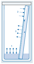
Figure.5: process in developing chamber1
In connection with the development process, the following aspects should be considered:1
With the exception of single component liquids (neat solvents), developing solvent and mobile phase are, strictly speaking, not the same. Their composition changes with progressing chromatography. Unfortunately the terms «developing solvent» and «mobile phase» are often used as synonyms. In the true sense only the liquid in the chamber should be called developing solvent, while the liquid moving through the layer constitutes the mobile phase. Only the composition of the developing solvent at the time when it is placed into the chamber is positively known. The processes (1) and (2) can be experimentally affected by:
• Fitting the chamber more or less completely with filter paper soaked with developing solvent.
• Waiting a certain time between the introduction of developing solvent into the chamber and the beginning of chromatography – chamber saturation.
• Allowing the plate to interact with the gas phase prior to chromatographic development, i.e. without contact to the developing solvent – preconditioning.
An interaction according to (2) and (3) can be effectively prevented by placing a counter plate at a distance of one or a few millimeters to the chromatographic layer. This is called «sandwich configuration». The further an equilibrium according to (1) and/or (2) has been established and the less different the components of the mobile phase are in respect to their adsorption behavior, the less pronounced is the formation of secondary fronts resulting from (4). In well-saturated chambers and on preconditioned layers secondary fronts are often not observed. In sandwich configuration and particularly in OPLC secondary fronts are very prominent.
During chromatography, components of the developing solvent, which have been loaded onto the dry layer via the gas phase according to (2), are pushed ahead of the true but invisible solvent front. Exceptions are very polar components such as water, methanol, acids, or bases. This results in RF values being lower in saturated chambers and particularly on pre-conditioned layers, than in unsaturated chambers and sandwich configurations.
Note that due to possible demixing of the solvents and possible beta fronts, development in sandwich configuration or in an unsaturated horizontal developing chamber works best with single component solvents or multi component solvents behaving like single component solvents.1
Consequences
Thin-layer chromatography in most cases proceeds in a non-equilibrium between stationary, mobile, and gas phase. For this reason it is very difficult to correctly describe the conditions in a developing chamber. Reproducible chromatographic results can only be expected when all parameters are kept as constant as possible. Chamber shape and saturation are playing a predominant role in this regard. Unfortunately this means that the chromatographic result is different in each chamber! There are neither «good» nor «poor» chambers! However, in some chambers the parameters can be better controlled, i.e. reproduced, than in others.1
Choosing a developing chamber
Selection of the «proper» chamber is done during method development and generally follows «practical» considerations such as which chamber is available, which one must be used due to an sop, or which one has been used in the past if a results comparison is to be made. however, a focus should also be on economical aspects such as time requirement and solvent consumption. a selection of glass chambers.1
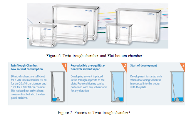
TWIN TROUGH CHAMBER
CAMAG twin trough chambers offer several ways to specifically affect the TLC/HPTLC separation in order to improve it.1
FLAT BOTTOM CHAMBER
The CAMAG Flat Bottom chamber permits the chromatogram to be developed under conditions of partial or complete saturation of the tank atmosphere with solvent vapors. the degree of layer pre-saturation cannot be controlled unless additional accessories are used.1
HORIZONTAL DEVELOPING CHAMBER
In the horizontal developing chamber, the hptlc plate is developed from both opposing sides towards the middle. This permits the number of samples to be doubled as compared with development in a tank, provided the separation distance of 45 mm, i.e. 50 mm minus 5 mm distance from the edge, is sufficient.
In the CAMAG horizontal developing chamber, a plate can be developed in the sandwich as well as in the tank configuration. The chamber is suitable for all kinds of solvents.1
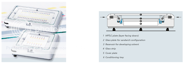
Figure.8: Horizontal developing chamber1
AUTOMATIC DEVELOPING CHAMBER ADC 2
The Automatic developing Chamber ADC 2 offers convenience, safety and reproducibility for isocratic developments of TLC/ HPTLC plates and foils with the format 20 x 10 cm.
The automatic developing chamber ADC 2 is the heart of an HPTLC system.It performs the development step fully automatically, reproducibly, and independentof environmental effects. the activity and pre-conditioning ofthe layer, chamber saturation, developing distance and final drying can bepre-set and automatically monitored by the ADC 2. two modes of operationare possible: stand-alone with input of parameters via keypad, orremote operation from WINCATS with process monitoring, documentationof operating parameters, and reporting.
Key features
• Fully automatic development of 20 x 10 cm TLC/HPTLC plates.
• A conventional 20 x 10 cm twin trough chamber is used for development. this way chamber geometry and chromatographic conditions of already existing analytical procedures can be retained, but environmental and operational effects are excluded.
• Operation in stand-alone mode or under WINCATS.
• The user is freed of all process monitoring responsibilities, operation is fully tracable.
• The option «humidity control» allows reproducible chromatography at defined activity of the layer.1
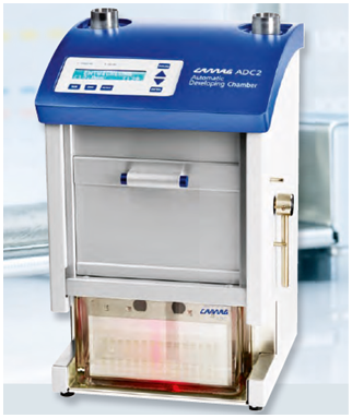
Figure.9: Automatic developing chamber ADC 21
THE AMD 2 SYSTEM: GRADIENT ELUTION IN THIN-LAYER CHROMATOGRAPHY
The CAMAG AMD procedure allows Thin-Layer chromatography to be utilized for tasks that could not be performed by TLC in the past.
Only the AMD procedure can be successfully employed for reproduciblegradient elution with silica gel as the stationary phase. In column liquid chromatography, gradient elution is common on reversed phases only because a silica gel column would call for a time consuming reconditioning or be irreversibly degraded, which is not acceptable in a technique dependingon multiple use of the stationary phase. In thin-layer chromatographythis is not relevant.
AMD = automated multiple development
The principle of the CAMAG AMD procedure
• The HPTLC plate is developed repeatedly in the same direction.
• Each successive run extends over a longer solvent migration distance than the one before.
• Between runs, the solvent is completely removed from the developing chamber and the layer is dried under vacuum.
• Each successive run uses a solvent of lower elution strength than that of the one used before. In this way, a stepwise elution gradient is formed.
• The combination of focusing effect and gradient elution results in extremely narrow bands. their typical peak width is about 1 mm. this means that, with the available separation distance of 80 mm, up to 40 components can be completely resolved, i.e. with base line separation.1
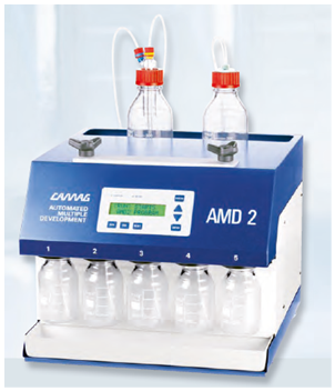
Figure.10: THE AMD 2 SYSTEM: gradient elution in thin-layer chromatography1
NOW YOU CAN ALSO PUBLISH YOUR ARTICLE ONLINE.
SUBMIT YOUR ARTICLE/PROJECT AT articles@pharmatutor.org
Subscribe to Pharmatutor Job Alerts by Email
FIND OUT MORE ARTICLES AT OUR DATABASE
DERIVATIZATION:
Post chromatographic Derivatization
It is an inherent advantage of Thin-Layer Chromatography that fractions remain stored on the plate and can be derivatized after chromatography. By derivatization substances that do not respond to visible or UV light can be rendered detectable. In many cases, substances or classes of substances can be identified by specific reagents.
1. Changing non-absorbing substances into detectable derivatives
2. Improving the detectability (lowering detection limits)
3. Detecting all sample components
4. Selectively detecting certain substances
5. Inducing fluorescence
From a technical point of view only one principal decision must be made: how to transfer the reagent to the plate?
Derivatization can be achieved with gas, by liquid spraying or dipping (immersion). In any case the reagent needs to be homogenously transferred to the chromatogram.
By immersing a TLC plate into the derivatizing reagent a very homogenous reagent transfer can be achieved. Dipping and withdrawing has to be performed smoothly in order to avoid tidemarks. Using the Chromatogramm Immersion Device the reproducibility of the derivatization step can be significantly improved compared to spraying. Furthermore, no fumes are generated during this derivatization technique and the exposure to hazardous chemicals is limited.
If the reagent is suitable, dipping should be preferred over spraying.
However, the fact is that spraying is most widely used for reagent transfer onto the TLC plate because it is simple and quick. No expensive equipment is necessary and only small volumes of reagent are needed. In addition spraying is very flexible and indispensable when reagents have to be applied in sequence. Also during method development, when searching for the most suitable reagent, spraying is more frequently mentioned.
Spraying on the other side generates substantial amounts of obnoxious and hazardous fumes, which must be carefully removed using e.g. the TLC Spray Cabinet.
During spraying, particularly for quantitative evaluation, it must be ensured that a homogenous fine spray mist is generated. Reproducibility of derivatization by spraying is greatly dependent on the skill of the operator. Most chemical reactions used in derivatization require heating for completion. The two principal heating devices are ovens and plate heaters. Ovens have two major shortcomings: One, fumes from derivatization agents can be corrosive and two, cross contamination may become an issue. It is therefore advantageous to use a TLC Plate Heater designed to homogenously heat the TLC plate to the selected temperature. If visualization is not required, derivatization may not be advantageous. For example, progesterone has a chromophor and absorbs UV light at 254 nm, it can thus be analyzed without derivatization. If necessary, the substance can be visualized by derivatization with sulfuric acid. The comparison of the standard deviation for the densitometric evaluation of derivatized and non-derivatized progesterone is given below. The best results are obtained without derivatization, derivatization by spraying yields the least reproducible results across the plate.1
CHROMATOGRAM IMMERSION DEVICE
For proper execution of the dipping technique, the chromatogram must be immersed and withdrawn at a controlled uniform speed. By maintaining a well defined vertical speed and immersion time, derivatization conditions can be standardized and «tide marks», which can interfere with densitometric evaluation, are avoided.
Key features
• Uniform vertical speed, freely selectable between 30 mm/s and 50 mm/s.
• Immersion time selectable between 1 and 8 seconds and indefi nitely.
• The device can be set to accommodate 10 cm and 20 cm plate height.
• Battery operated, independent of power supply.1
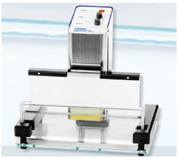
Figure.11: TLC/HPTLC SPRAYER1
TLC/HPTLC SPRAYER
The TLC sprayer consists of a charger and a pump unit with two kinds of spray heads.
• spray head type A is for spray solutions of normal viscosity, e.g. lower alcohol solutions.
• spray head type B is for liquids of higher viscosity, e.g. sulfuric acid reagents.
Key features
• Easy to use, with electro-pneumatic spray function.
• Formation of fi ne aerosol with particles of 0.3 to 10 μm.
• Homogenous distribution with low reagent consumption.1
REAGENT SPRAYER
This all glass reagent sprayer is a low cost alternative to the TLC/HPTLC sprayer. It comes with a rubber pump but may also be operated from a compressed air or nitrogen supply.1
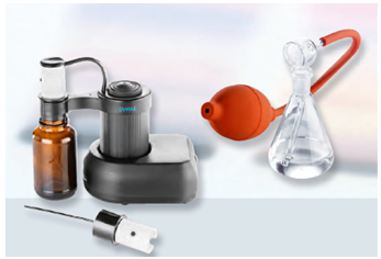
Figure.12: Reagent Sprayer1
TLC SPRAY CABINET
The TLC spray cabinet ensures the complete removal of reagent mist while spraying tlc plates. there is no deflection of the spray mist before it reaches the chromatogram, an effect often occurring in a normal laboratory fume hood. The TLC spray cabinet is made of PVC. The blower, a radial fan driven by a motor outside of the fume duct, produces airflow of 130 cubic feet (3.7 cubic meter) per minute. The bottom of the spray cabinet has a built in tray, which is removable for easy cleaning.
Dimensions: 470 x 490 x 490 mm (width x depth x height).1
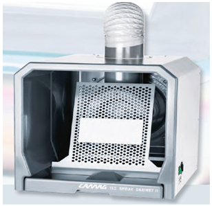
Figure.13: TLC spray cabinet1
TLC PLATE HEATER
The TLC plate heater III is designed for heating TLC plates to a given temperature, while ensuring homogenous heating across the plate. The TLC plate heater III has a CERAN® heating surface which is resistant to all common reagents and is easily cleaned. The 20 x 20 cm heating surface has a grid to facilitate correct positioning of the TLC plate. programmed and actual temperature are digitally displayed. The temperature is selectable between 25 and 200 °c. The plate heater is protected from overheating.1
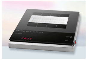
Figure.14: TLC plate heater1
QUANTIFICATION
Most modern HPTLC quantitative analysis are performed in situ by measuring the zones of samples and standards using a chromatogram spectrophotometer usually called a densitometer or scanner with a fixed sample light beam in the form of a rectangular slit. Generally, quantitative evaluation is performed with the TLC Scanner 3 using WINCATS software. It can scan the chromatogram in reflectance or in transmittance mode by absorbance or by fluorescent mode; scanning speed is selectable up to 100 mm/s. Spectra recording is fast. Calibration of single and multiple levels with linear or nonlinear regressions are possible. When target values are to be verified, such as stability testing and dissolution profile, single level calibration is suitable. Concentration of analyte in the sample is calculated by considering the sample initially taken and dilution factors.1
DOCUMENTATION
Each developed plate is documented using digital documentation system under UV light at 254 nm, UV light at 366 nm, and white light. If a type of light does not produce usable information, that fact must be documented. If a plate is derivatized, images are taken prior and after derivatization.1
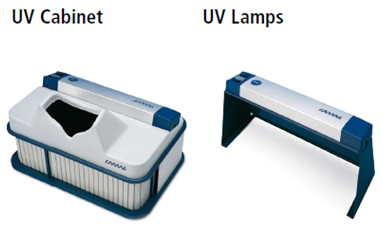
Figure.15: UV Cabinet and UV Lamps1
REFERENCE
1. CAMAG, 2010-2011. Basic equipment for modern thin layer chromatography. Switzerland: Camag.
Available from: camag.com/downloads/free/brochures/CAMAG-basic-equipment-08.pdf
2. CAMAG, 2010-2011. Instrumental thin layer chromatography. Switzerland: Camag.
Available from: camag.com/downloads/free/brochures/CAMAG_TLC10-11_E.pdf
3. Patel, R.B. and Patel, M.R. and Patel, B.G. (2011) Experimental Aspects and Implementation of HPTLC. In: Shrivastava, M.M. HPTLC. New York: Springer, pp. 41- 54.
4. Shrivastava, M.M. (2011) An Overview of HPTLC: A Modern Analytical Technique with Excellent Potential for Automation, Optimization, Hyphenation, and Multidimensional Applications. In: Shrivastava, M.M. HPTLC. New York: Springer, pp. 3- 24.
NOW YOU CAN ALSO PUBLISH YOUR ARTICLE ONLINE.
SUBMIT YOUR ARTICLE/PROJECT AT articles@pharmatutor.org
Subscribe to Pharmatutor Job Alerts by Email
FIND OUT MORE ARTICLES AT OUR DATABASE