

 About Authors:
Lila dhar*1,Surender Jalandra
1Seth G. L. Bihani S. D. College Of Technical Education,
Institute Of Pharmaceutical Sciences & Drug Research,
Gaganpath, Sri Ganganagar, Rajasthan 335001
*ldbudania@gmail.com
ABSTRACT
Electron paramagnetic resonance spectroscopy (EPR) is a powerful tool for investigating paramagnetic species, including organic radicals, inorganic radicals, and triplet states. The basic principles behind EPR are very similar to the more ubiquitous nuclear magnetic resonance spectroscopy (NMR), except that EPR focuses on the interaction of an external magnetic field with the unpaired electron(s) in a molecule, rather than the nuclei of individual atoms. EPR has been used to investigate kinetics, mechanisms, and structures of paramagnetic species and along with general chemistry and physics, has applications in biochemistry, polymer science, and geosciences. The use of cavity stabilised Impatt diode oscillators for ESR spectroscopy is discussed in different experimental conditions: i.e. as microwave sources in reflection cavity homodyne spectrometers, and as marginal oscillators in which the oscillator cavity (a TE011 cylindrical cavity) is the observing cavity. The sensitivity of this second configuration has been theoretically evaluated for the case in which the Impatt itself is used as a detecting element and in which an external detector is used. For each situation the sensitivity has been measured with a DPPH sample at various power levels giving a sensitivity which is comparable with the best commercial units.
[adsense:336x280:8701650588]
Reference Id: PHARMATUTOR-ART-1579
ELECTRON SPIN RESONANCE
Introduction
Also known as….
Electron Paramagnetic Resonance(EPR)
Electron Magnetic Resonance(EMR)
What Is ESR???
· It is a branch of absorption spectroscopy in which radiation having frequency in microwave region is absorbed by paramagnetic substance to induce transition between magnetic energy level of electron with unpaired spin.
· Magnetic energy splitting is done by applying a static magnetic field.
INSTRUMENTATION OF ESR SPECTROSCOPY
(1) KLYSTRONS
Klystron tube acts as the source of radiation. It is stabilized against temperature fluctuation by immersion in an oil bath or by forced air cooling. The frequency of the monochromatic radiation is determined by the voltage applied to klystron. It is kept a fixed frequency by an automatic control circuit and provides a power output of about 300 milli watts.
(2) WAVE GUIDE OR WAVEMETER
The wave meter is put in between the oscillator and attenuator to know the frequency of microwaves produced by klystron oscillator. The wave meter is usually calibrated in frequency unit (megahertz) instead of wavelength. Wave guide is a hollow, rectangular brass tube. It is used to convey the wave radiation to the sample and crystal.
(3) ATTENUATORS
The power propagated down the wave guide may be continuously decreased by inserting a piece of resistive material into the wave guide. The piece is called variable attenuator and used in varying the power of the sample from the full power of klystron to one attenuated by a force 100 or more.
[adsense:468x15:2204050025]
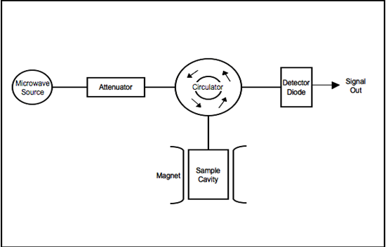
Block diagram of a typical spectrometer
(4) ISOLATORS
It is a non-reciprocal device which minimizes vibrations in the frequency of microwaves produced by klystron oscillator. Isolators are used to prevent the reflection of microwave power back into the radiation source. It is a strip of ferrite material which allows micro waves in one direction only. It also is being stabilizing the frequency of the klystron.
(5) SAMPLE CAVITIES
The heart of the ESR spectrometer is the resonant cavity containing the sample. The sample is contained in a resonance cavity. Rectangular TE120 cavity and cylindrical TE011 cavity have widely been used. In most of the ESR spectrometers, dual sample cavities are generally used. This is done for simultaneous observation of a sample and a reference material. Since magnetic field interacts with the sample to cause spin resonance the sample is placed where the intensity of magnetic field is greatest. A measure of quality of the cavity is ‘Q factor’ which is defined as
The sensitivity of the spectrometer is directly proportional to this value of Q.
Rotable cavities and dual cavities have also been used respectively for study in anisotropic effect in single crystal land simultaneous spectroscopic observation of a sample and standard.
(6) COUPLERS AND MATCHING SCREWS
The various components of the micro wave assembly to be coupled together by making use of irises or slots of various sizes.
(7) CRYSTAL DETECTORS AND HOLDERS
A Silicon crystal detectors, which converts the radiation in D.C., has widely been used as a detector of microwave radiation. Microwave Bridge such as magic T and hybrid ring variety are most common.
(8) MAGNET SYSTEM
The resonant cavity is placed between the poles pieces of an electromagnet. An electro magnet capable of producing magnetic field of at least 5000 gauss is required for ESR. The field should be stable and uniform over the sample volume. The stabilityof field is achieved by energizing the magnet with a highly regulated power supply.
The ESR spectrum is recorded by slowly varying the magnetic field through the resonance condense by sweeping the current supplied to the magnet by the power supply. This sweep is usually accomplished by with a variable speed motor drive. Both the magnet as well as the power supply may require water cooling.
(9) MODULATION COIL
The modulation of the signal at a frequency consistent with good signal noise ratio in the crystal detector is accomplished by a small alternating variation of the magnetic field. The variation is produced by supplying an A.C. signal to modulation coil oriented with respect the sample in the same direction as the magnetic field. If the modulation is of low frequency (400 cycles/sec or less), the coils can be mounted outside the cavity and even on the magnet pole pieces. For higher modulation frequencies, modulation coils must be mounted inside the resonant cavity or cavities constructed of a non-metallic material e.g., Quartz with a tin silvered plating, because metallic penetration is not very effective in case of higher modulation frequencies.
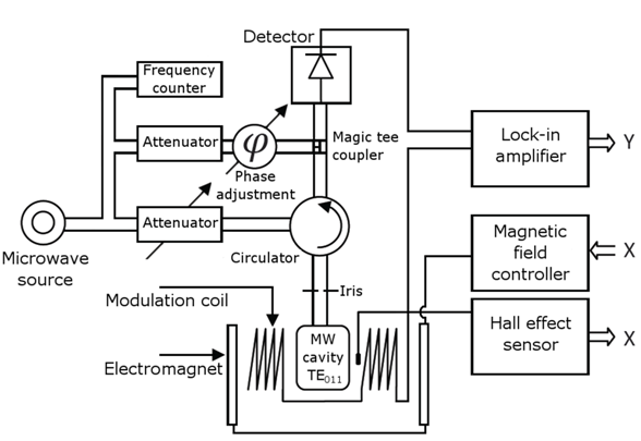
SCHEMATIC DIAGRAM OF AN ESR SPECTROMETER
(10) DISPLAY DEVICES
In order to adjust the spectrometer and to observe the signal, a cathode ray oscilloscope has been employed. A strip chart or X-Y recorder is used for recording the signal.
EPR spectra are usually displayed in derivative form to improve the signal-to-noise ratio.
REFERENCE
1. Chatwal G.R, Anand S.K. Instrumental Methods Of Chemical Analysis,(Analytical Chemistry) Published By Himalya Publishing House, 5th Revised And Expended Edition Reprint 2005 Page No. 2.245-2.252
2. Conners K.A, A Text Book Of Pharmaceutical Analysis, 3rd Edition 2002, Published By Wiley And Sons, New York, Page No. 299-301
3. Kemp William, Organic Spectroscopy, 3rd Edition Reprint 2005, Published By Palgrave Publication, New York Page No. 236-240
4. Finar I.C. Organic Chemistry, 5th Edition, Published By John Wiley And Sons, New York, Page No. 27, 213
5. Sharma B.K, Instrumental Methods Of Chemical Analysis, Published By Goel Publishing House, Meerut, Page No577-579
6. Willard Hobart H. Et Al, Instrumental Methods Of Chemical Analysis, 7th Edition, CBS Publishers And Distributers, New Delhi Page No115-116, 386-392.
NOW YOU CAN ALSO PUBLISH YOUR ARTICLE ONLINE.
SUBMIT YOUR ARTICLE/PROJECT AT articles@pharmatutor.org
Subscribe to Pharmatutor Alerts by Email
FIND OUT MORE ARTICLES AT OUR DATABASE